Disassembly

Taking the speedo apart is quite easy and only a few tools are required I suggest that you do the job on a clean (ferrous free)
surface, and have a range of plastic take away boxes to put the parts in.
There only two special tools that I would recommend, a pair of small levers (easily made) to help remove the pointer or needle
from a stubborn arbour (without damage) . Secondly a wood block with a 16mm diameter hole in the centre. Two pairs of tweezers
will also be useful. An instrument screwdriver and a pair of instrument pliers. The eyeglass is handy to look at small parts.
Remove the speedometer from the car.
In a different place to your disassembly area, remove the surface dirt. Using a small wire brush clean out the inside of the
bezel lip, as the bezel lip is a bit like the bayonet fitting on a light bulb, with a bit of care the bezel can be twisted apart
from the speedometer housing body.
Prise out the blue plastic light shield.
Unscrew the two 3BA screws on the back of the housing and with a bit of care and twisting the speedo body can be removed from the housing.
The housing can be put threaded section down into the wood block, now you can have a good look at the speedo. The speedo body is an
aluminium or possibly a mazac casting. There are two major bits hanging off the casting the odometer plate and the speedometer assembly.
With the speedo at rest i.e. the needle resting on the stop, I mark the side of the housing with a felt tip pen and adjacent to this
mark the drag cup so that you can reassemble the pointer in what should be the correct position.

Slip a thin bit of card between the dial face and the needle boss and using a pair of levers under the needle gently prise the needle
from the arbour / shaft, this should be quite easy, the card allows the levers to bear on the card and not the dial! this should stop
the dial face from being scratched.

Remove the two 10BA 7/32 screws from the speedo dial allowing the dial to be removed from the two supporting posts. Put the dial away
safely, I suggest it is put in a small plastic bag to prevent the dial face being damaged.

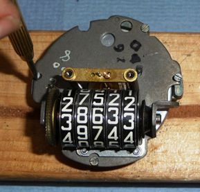
Turn the speedo on its side and take a close look at the odometer ratchet drive the odometer is driven by a
ratchet which is impulsed via a cam peg fitted to a tufnol gear driven from a brass worm on the magnetic spinner assembly.
The picture shows the small spring steel retaining part already released from the cam peg. There is a small 1/2 inch long spring
which is partially hidden behind the odometer supporting arm. This spring tensions the odometer ratchet arm against the ratchet ,
this spring needs to be carefully removed, a very small set of tweezers comes in handy for this job. Be careful and do not loose the
spring.

The spring ratchet pawl arm and the spring steel clip will need to be released, take of these bits as they can get lost.
The next operation is a bit delicate but can be done with care!
 Undo the brass taper pin which is securing the return hair spring to the dial posts. The hair spring is delicate and is colleted on to
the pointer / needle arbour. Once the tapered brass pin is removed the hair spring should revolve around on the arbour.
Undo the brass taper pin which is securing the return hair spring to the dial posts. The hair spring is delicate and is colleted on to
the pointer / needle arbour. Once the tapered brass pin is removed the hair spring should revolve around on the arbour.
Undo the four 9BA by ¼ inch screws which retain the stator plate to the cradle. When the screws have been removed it
is be possible to separate the stator plate from the cradle, taking care of the hair spring.

With a bit of jiggery it is now possible to separate the remove the drum spindle or drag cup assembly from the odometer plate with care,
Put the drum assembly on one side after having a look at the pivots on the ends of the needle shaft. It is likely that they will be
dirty and might be worn. Do not try and remove the hair spring unless you really have to, there is no point unless it is damaged.

The photograph shows the key hole plate the speedometer cradle separated from the magnet and worm assembly
 The photo shows the speedometer disassembled. As it said in the good book re- assembly is the reverse of disassembly. Which of course is true The needle shown in this photograph is not correct.
